Multibeam echosounder
Patch Test – Tilted Head Line Spacing
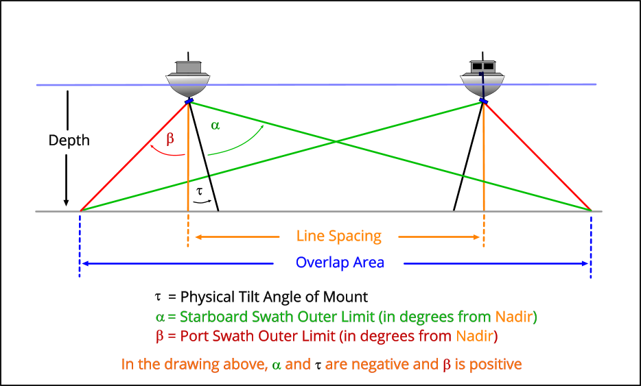
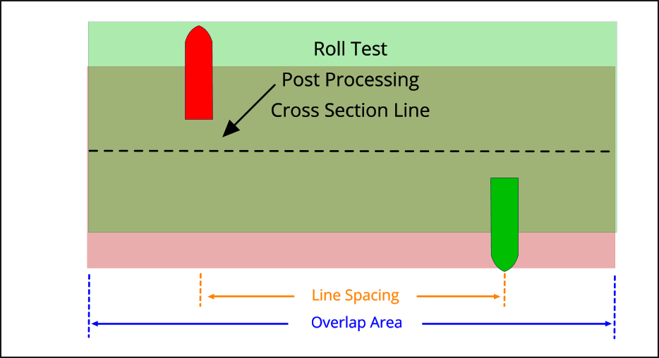
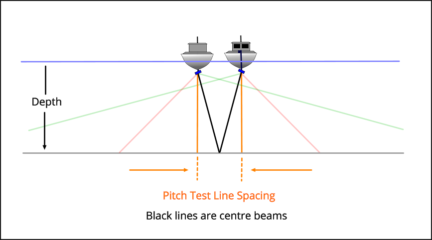
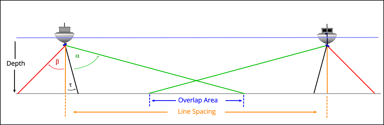
Calculate roll, pitch, and yaw patch test line spacings for a tilted sonar head, based on swath geometry and desired overlap.
Sonar Parameters
Range: −100 – 100 | Starboard = positive
Range: −89 – 89
Range: −75 – 75
Range: −89 – 89
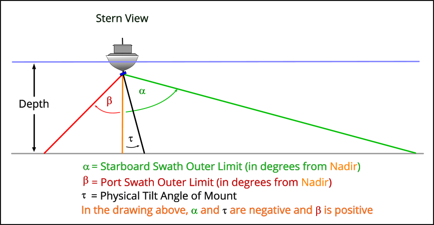
Roll Patch Test
Range: 1 – 5,000
Roll Line Spacing (survey units)
—
Total Overlap Width (survey units)
—
Pitch Test
Uses the average depth and mount tilt entered above.
Pitch Line Spacing (survey units)
—
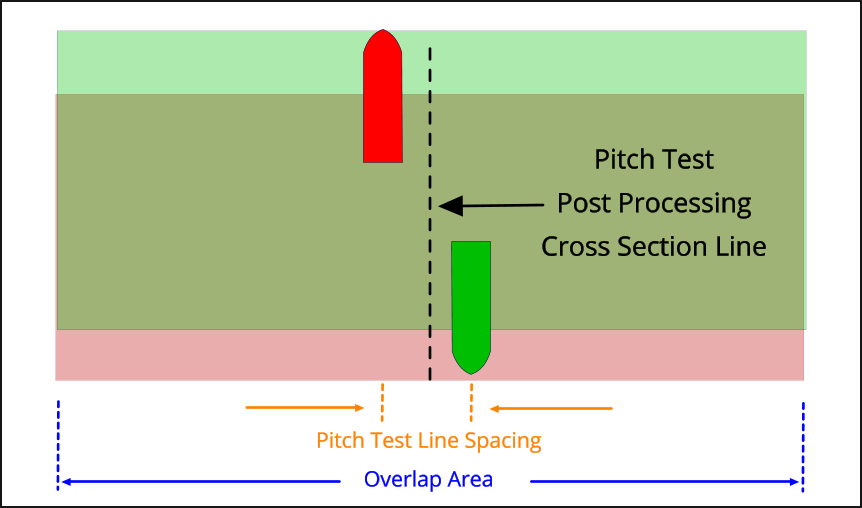
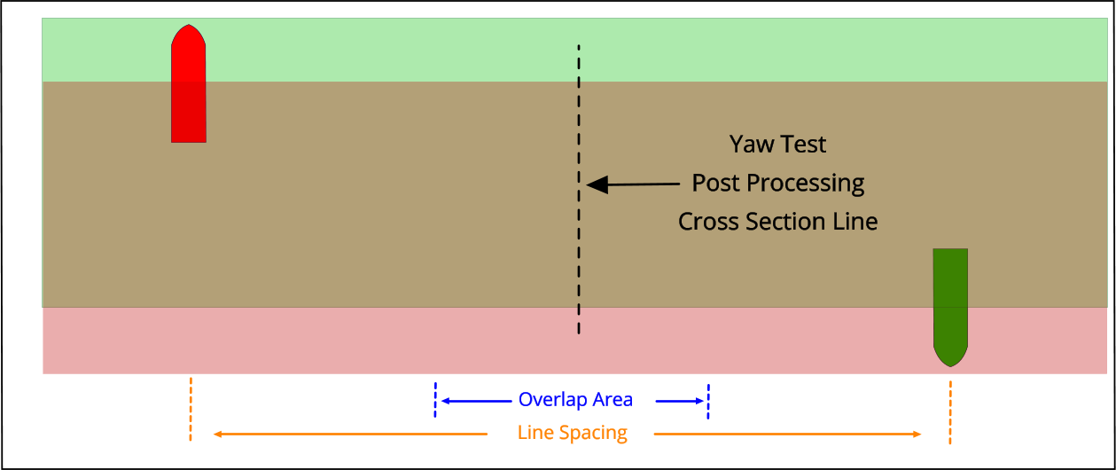
Yaw Test
Range: 1 – 5,000 | Shallowest point on the lines
Range: 1 – 50
Yaw Test Line Spacing (survey units)
—
These results are informational only and are intended as a starting point for patch test line planning with a tilted sonar head. Actual line spacings should be verified against field conditions and sonar documentation. MosaicHydro accepts no liability for decisions made based on this tool.